
Our rectifiers and power supplies are configured to match your process. Follow the three-step guide: control, metering, then specific options.
Operate the rectifier manually through an interface, or automatically through a setpoint signal.
Measure and totalise the energy used by your processes, at the level of control you need.
Fine-tune the electrical behaviour of your rectifier to the demands of your application.
Reverses the direction of the current in the circuit — a real asset when starting up your bath.
Optimal accuracy across two orders of magnitude, to cope with varying currents.
Regulation measured at the load terminals: compensates for the voltage drop in the power cables.
Dual-output rectifier: balanced current sharing from a single setpoint, with simplified wiring.
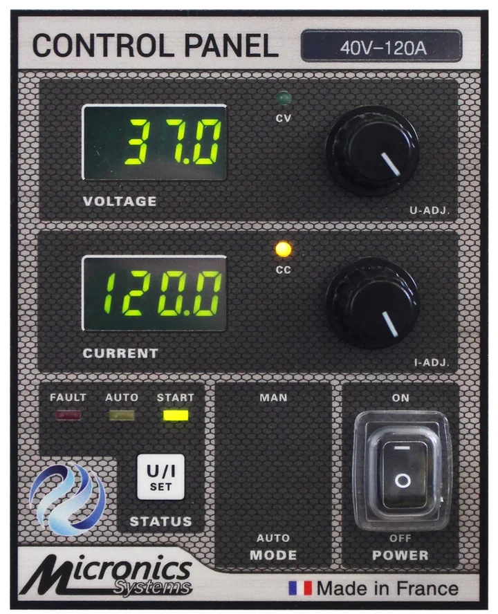
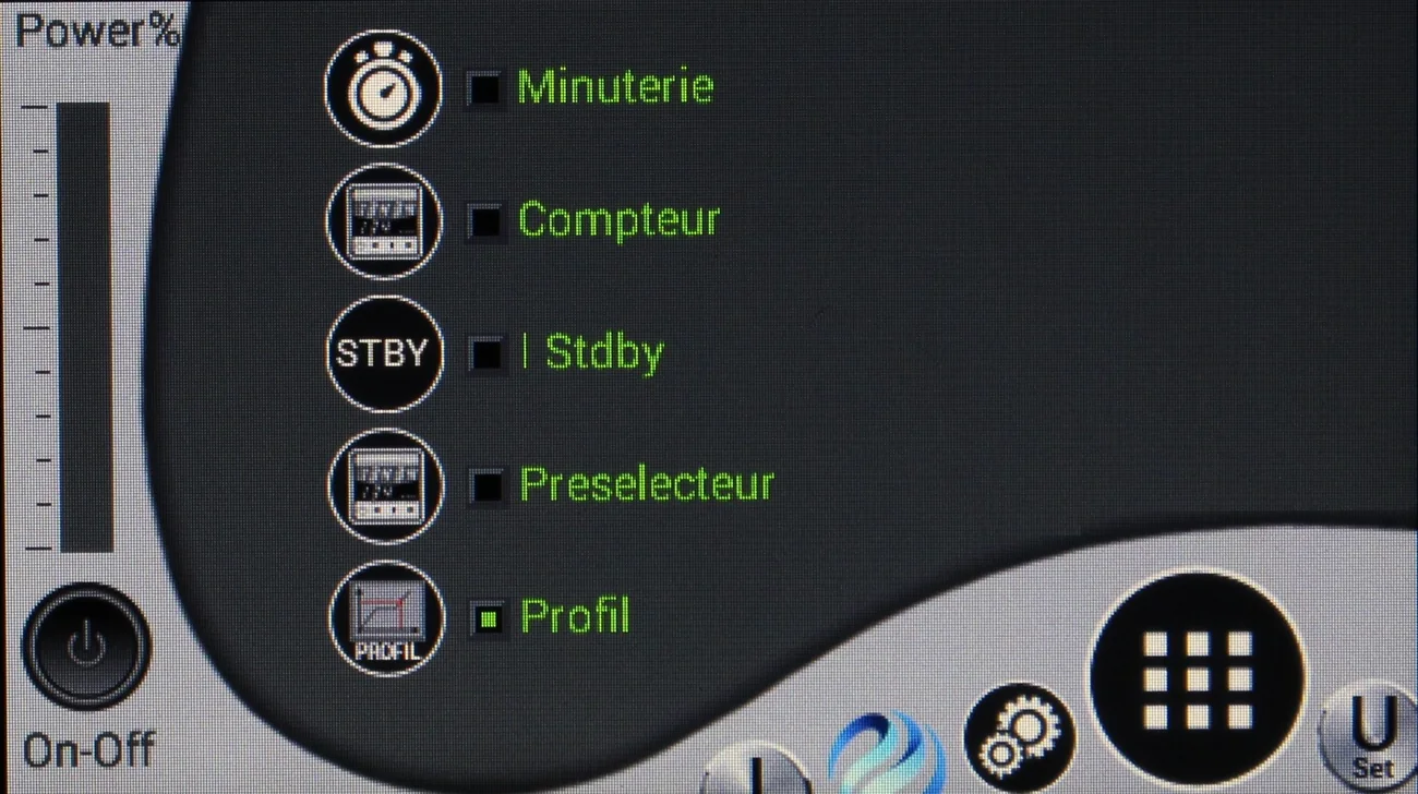
Click the markers to locate each function on our interfaces. The exact layout depends on the model and on the format chosen (wall-mounted, enclosure, cabinet or rack).
Control Panel — manual control on the front panel.
MicronX touchscreen — operation, metering and cycles from the interface. Drag the image to explore it.
Not all of these functions coexist on the same machine: the configuration is defined together with you.
Control, metering and specific options are defined machine by machine. Start with the range that matches your power requirement.
The MGT2 to MGT5+ range, compact and wall-mounted, to equip a tank or a surface finishing line.
See the range Power cabinetsThe cabinet-mounted MGP models, when the power required exceeds what a wall-mounted enclosure can handle.
See the range Scalable powerA cabinet that grows with the installation, with control HMI, air or water cooling and remote diagnostics.
See the range Regulated power suppliesFor laboratory, R&D and test bench use, with 2- or 4-quadrant operation depending on the model.
See the range 19″ rackThe rack format, to be integrated into a test cabinet or an existing enclosure.
See the range Outside the standard catalogueBack-of-cabinet module and pulse generators, designed to specification.
See the rangeNot every option is available on every range, and some depend on the rating chosen: tell us your process and your model and we will confirm what is possible. See the full catalogue
Some common pairings between a process requirement and the option that answers it. Each line links to the page for that process.
These pairings are pointers: the final configuration depends on your installation, your throughput and your level of automation. See our industries
A Micronics rectifier is not an off-the-shelf product: it is designed and assembled in Villette-d'Anthon for one specific line, bath or test bench. The options above are therefore not accessories added afterwards: they are part of the specification, just like the output voltage and current. That is why the guide runs in this order: first how the setpoint is given to the rectifier, then how the energy delivered is measured and totalised, and finally the functions that change its electrical behaviour.
In practice, three questions are usually enough to frame a configuration. They require no knowledge of power electronics: they simply describe the way you work.
An operator standing at the machine does not have the same needs as a line PLC sending a 0-10 V, 4-20 mA or fieldbus signal. That is what decides between a front-panel interface and remote control.
A totaliser tells you what has passed; a preset counter lets you work to a predefined quantity; a log exported to a USB stick feeds a quality file. Three levels of requirement, three different fits.
The distance between the rectifier and the load, the gap between the lowest and the highest current, the need to reverse the current or to ramp the voltage up gradually: these constraints point straight to the specific options.
You do not need to have made up your mind before talking to us. Describe your process, your installation constraints and your level of automation: we will propose a reasoned configuration, and then handle the maintenance, the repairs and the training of your teams.
Our experts support you from study through to commissioning.